The computer simulation program TRANSISTOR with a model about an active electronical circuit with one transistor.
Many mathematical models of a transistor are known. Some of these models are matrix-models, treating the transistor as a black box, presenting sets of values of output variables as a result of sets of values of input parameters like input impedance, voltage gain etc. Other models simulate the transistor in a more transparent way. In these models, the transistor is described by means of an electronic circuit. The models can be used in order to study the transistor's behaviour in a circuit in a dynamic way by changing some parameters of the circuit.
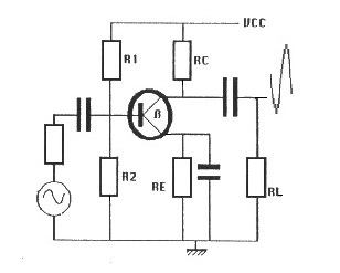
Figure 1. The active electronical circuit with one transitor. This circuit amplifies an input signal to an output signal.
The model of a transistor, implemented in the prototype TRANSISTOR, belongs to the second type of models. It describes the behaviour of a transistor in a normal low signal amplifier circuit: u output=f(u input). (See figure 1, 2, 3 and 4.) The model has been developed for educational applications by Min and Malhotra (1988) and Min and Van Leeuwen (1990, not published).
Figure 2. The circuit with the transistor with the input (ui) and output (uo) of all the versions of the computer simulation program TRANSISTOR. RC and RE are important for the DC flow (IC0) through the transistor, and R1 and R2 for the DC voltage of the basis of the transistor (UB).
Educational value
Simulations of electronic networks may be useful in the physics or electronics curriculum as a training before starting real experiments. The consultation of content specialists, curriculum specialists and specialists in didactics would be required in order to obtain the information needed for the improvement of the prototype in order to make it suitable for use in a didactic environment. Users of TRANSISTOR learn to see the difference between the DC en the AC behavior of this transistor circuit.
Nevertheless, prototypes similar to TRANSISTOR may prove very useful in everyday physics teaching to replace expensive or difficult experiments.
Model description
TRANSISTOR has been first implemented in MacTHESlS by Malhotra in 1988. The purpose of the implementation was to test the performance of the design system with respect to the implementation of models originating from the subject of Physics. Min and Van Leeuwen have implemented TRANSISTOR in MacTHESlS in 1990; later sometimes in JavaTHESIS; see figure 5 and 6. The default values of the parameters and the starting values of his model are:
A =  0.01               <- V
f =  100.0              <- Hz
ui   =  0.0             <- V
beta =  200.0
IC0 =  1.0              <- mA (the DC flow)
q =  1.6E-19            <- Asec
K =  1.38E-23           <- J/K
T =  100.0              <- K
S =  40.0*IC0           <- (q / K.T).IC0 = 40.0
rb =  beta/S            <- 5 kOhm

Ucc =  12.0                       <- V
IB0 =  IC0/beta                   <- 1/200=0.005 mA
IE0 =  (beta + 1)*IB0             <- (200+1)0.05 = 1.005 mA
RC =  4.0                         <- kOhm
R2 =  56.0                        <- kOhm
RE =  (0.5*Ucc - IC0*RC)/IE0      <- 2/1.005 kOhm
Ir =  (0.7 + RE*IE0)/R2           <- 2.71/56 = 0.04839 mA
R1  =  (Ucc-0.7-RE*IE0)/(IB0+Ir)  <- 174.0 kOhm

ib  =  ui*S/beta
uo =  -beta*ib*RC
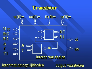
Figure 3. The black box of the model of the computer simulation program TRANSISTOR with the input (the parameters) and output (the variables).
The most essential parts of the first version of the model (here written in Pascal) are:
Repeat
  t := t + dt;
  ui := A * sin (2 * 3.1418 * f * t);
  S := 40 * IC0;
  IB0 := IC0 / beta;
  IE0 := (beta+1) * IB0;
  RE := (0.5*Ucc - IC0*RC) / IE0;
  Ir := (0.7 + RE*IE0)/R2;
  R1 := (Ucc - 0.7 - RE*IE0) / (IB0 + Ir);
  i1:=ui/R1;
  i2:=ui/R2;
  ib := ui * S / beta;
  ii := i1+i2+ib;
  uo := -beta*ib*RC;
  io :=uo/RC;
Until t > Tmax;
The most essential parts of the last version of the model (here written in Java) are:
for (....)
{
  t := t + dt;

  ui := A * Math.sin (2 * 3.1418 * f * t);
  if (ui>0.01) ui = + 0.01;
  if (ui<0.01) ui = - 0.01;

  UB = Ucc*R2/(R1+R2);
  URE = URE + ((UB - 0.7) - URE)*0.03;
  IE0 = URE/RE;
  IC0 = IE0;
  UC = Ucc - IC0*RC;

  ui1 = ui1 + (ui - ui1)*0.2;
  uo = -40*IC0*RC*ui1;

  U0 = UC + uo;
};
Figure 4. The model of the computer simulation program TRANSISTOR with the DC and the AC component. RC and RE are the important resistances for the flow trough the transistor (IC0). R1 en R2 are important for the voltage of the basis of the transistor (UB). (The 'DC components'.)
The AC-components are not the same of the DC components. The uo is a function of RC, R1, R2 and ui. Here uo = -40*IC0*RC*ui1. The prototype TRANSISTOR is first designed according to the description of the student's environment of MacTHESlS. In this application three windows are present. In the other versions mostly two window are visualized. The circuit consists a 'standard' transistor, some resistors and a function generator. See the online example:
Online example 1. the microworld of TRANSISTOR (version Adapt-project, 2004, 'veelBekend.html' ipv. 'Applet.html')
Figure 5. The 'input-window' with 'inclick-regio's' (yellow) and the 'output-window' of the computer simulation program TRANSISTOR, version 2000 with grahical output-signal, uo(t), and graphical input-signal ui(t).
Students can change the form of the input (sinus, block or pulse), the frequency and the amplitude of the input on the circuit on in other regions by clicking on the function generator or something. Furthermore, the properties of the electronic network can be changed by clicking sometimes in one of the resistors or some part of the transistor.
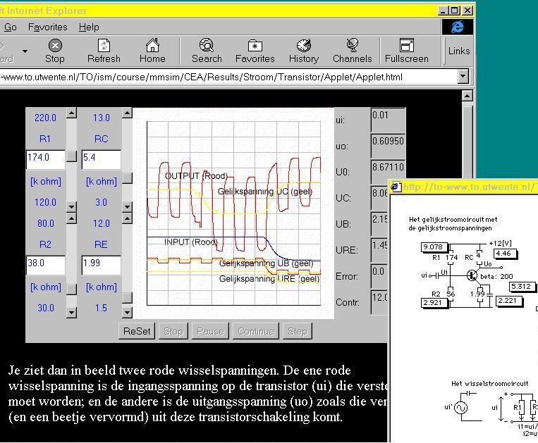
Figure 6. The 'output-window' with with grahical output-signal, uo(t), and graphical input-signal ui(t) of the computer simulation program TRANSISTOR, version 2002 with 4 menu-bars for model-interventions. Right: the other window with the model. In a parallel window - hiden in this screendump - exercises and instructions.
REFERENCES:
Other facts about TRANSISTOR [Rik Min, 1996 - 2004]
Enschede, 1988, 1996 - 2002. Gerestaureerd in 2020