Instruction
In this column you find some instruction of how to use and operate technically with the simulationThe control panel
The simulation is displayed in the middle part in the form of curves; each curve has a different colour and is corresponding to one of the output variables; each curve is a consecutive record of the values of the corresponding variable; you can use the simulation by the 5 buttons at the bottom of the middle part.To start the simulation you should press the "Start the simulation" button. The simulation window is always active.
To run the simulation you should press the "Continue" button at the bottom line of the simulation window. To make the simulation goes systematic press the 'Step' button.
When the simulation stopped or just stops then you have two possibilities - to restart it by pressing "Continue" or to reset all input variables to default by pressing, "Reset".
When you click "Reset" the graphs is disappear.
The graphical and numerical output
The output variables are displaying in the right column; the current value of each output variable is displaying in the box next to it.Possible results may be values of six output variables ui (input voltage), uo (output voltage), UR2 (R2 voltage), URC (RC voltage), URE (RE voltage) and T (time). They presented at the right side of the simulation window.
The interventions
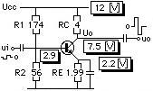
The input parameters are displayed in the left column; each parameter is displayed with its name, unit, maximum value, minimum value, and a box indicating the current value of the parameter. The main point of using the simulation is to change input values. You can do it with special scrolls at the left side of the simulation window.There are 4 parameters in this model, 4 resistors, RE, RC, R1 and R2.
When you will start practice with the simulation by trying to perform tasks then you should preset these input values to some values to achieve desired results.
Simulation
In this column you find an interactive microworld about a transistor circuit for learning the influences on DC and AC voltages in relation to resistances.The microworld
This microworld simulates the RC circuit: one transistor and 4 resistors with 3 capicitors. It is a so called java-applet with 4 online interventions and some graphical output. If you click on the button you see the microworld with the 4 parts: part 1, the interventions (R1, R2, RE and RC), part 2, the control panel, part 3, the graphical output and part 4, the numerical output.The model

Exercises
In this column you find some exercises and answers. Please note the effects of the output: increased, decreased or unchanged.Exercise 1
What happen if you increase RE?Exercise 2
What happen if you decrease RE?Exercise 3
What happen if you increase RC?Exercise 4
What happen if you decrease RC?Exercise 5
What happen if you increase R1?Exercise 6
What happen if you decrease R1?Exercise 7
What happen if you increase R2?Exercise 8
What happen if you decrease R2?Answers
Below you will find some remarks about the answers.If you increase RE: xxx.
If you decrease RE: xxx.
If you increase RC: xxx.
If you decrease RC: xxx.
If you increase R1: xxx.
If you decrease R1: xxx.
If you increase R2: xxx.
If you decrease R2: xxx.