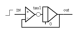
Introduction in systems and controlled systems
This page contains 4 versions not-controled systems
1. a zero order system (without an integrator)
2. a first order system (with 1 integrator)
3. a second order system (with 2 integrators)
4. a third order system (with 3 integrators)
and 4 versions of a controlled second order system
a. a controlled second order system (with 2 integrators and feedback)
b. a controlled second order system (PI) (with 2 integrators, P, I and on/off feedback)
c. a controlled second order system (PID) (with 2 integrators, P, I and delayed feedback)
1. a zero order system
 |
t = t + dt;
OUT=IN*Constante;
|
If the only parameter (constante) has a certain value (0.8) and IN is setting on a value (2.0), then you see the output OUT goes directly to a certain value (1.6). IN is red colored.
2. a first order system
 |
t = t + dt;
dOUTdt=(IN-OUT)/tau;
OUT=OUT+dOUTdt*dt;
|
If IN is setting on a certain value (e.g. 6.6), then you see the output OUT reaching to that value of IN on a characteristic way in a certain amount of time. The value of OUT never will be more than the value of IN.
3. a second order system
 |
t = t + dt;
dOUT1dt=(IN-OUT1)/tau1;
OUT1=OUT1+dOUT1dt*dt;
dOUT2dt=(OUT1-OUT2)/tau2;
OUT2=OUT2+dOUT2dt*dt;
|
If IN is setting on a certain value (e.g. 6.6), then you see the output OUT2 reaching to that value of IN on a characteristic way in a certain amount of time. The value of OUT2 never will be more than the value of IN.
4. a 3th order system
 |
t = t + dt;
dOUT1dt=(IN-OUT1)/tau1;
OUT1=OUT1+dOUT1dt*dt;
dOUT2dt=(OUT1-OUT2)/tau2;
OUT2=OUT2+dOUT2dt*dt;
dOUT3dt=(OUT2-OUT3)/tau3;
OUT3=OUT3+dOUT3dt*dt;
|
If IN is setting on a certain value (e.g. 6.6), then you see the output OUT3 reaching to that value of IN on a characteristic way in a certain amount of time. The value of OUT3 never will be more than the value of IN.
**) Be careful: sometimes the parameters are 'multipliers' (c*x) and sometimes the are 'dividers' (x/c). Here tau1 or tau2 is mostly 1/tau1 or 1/tau2. (See also eBook of Min about analogue schemes.)
Controlled systems
a. a controlled second order system
Situatie a: 
Situatie b: 
|
t = t + dt;
e = IN - x;
dOUT1dt=(e-OUT1-OUT2)/tau1;
OUT1=OUT1+dOUT1dt*dt;
dOUT2dt=OUT1/tau2;
OUT2=OUT2+dOUT2dt*dt;
x = OUT2*tau0;
|
If IN, the 'set point', is setting on a certain value (e.g. 6.6), then you see the output OUT2 (blue colored) is following the value of IN. The value of OUT2 can be higher or lower than the value of the setpoint IN. The 'steady state' of the value of OUT2 depends on the parameter tau0. Tau0 definites the value of the output OUT2.
b. a controlled second order system (by a PI)
 |
t = t + dt;
if (Sch>0.5) {Sch=1.0;}
if (Sch<0.5) {Sch=0.0;}
PV=Sch*PV0;
P = 0.05*(SP-PV);
dydt=P/Ti;
y=y+dydt*dt;
dOUT1dt=(y-OUT1)/tau1;
OUT1=OUT1+dOUT1dt*dt;
dPV0dt=(OUT1-PV0)/tau2;
PV0=PV0+dPV0dt*dt;
|
If SP, the 'set point', is setting on a certain value (e.g. 6.6), then you see the output PV0 (green colored) reaching to that value of SP. If the switch 'Sch' is not closed the value of the output PV0 become much more higher than the value of the set point SP. The output is growing and growing all the time.
If you close the switch 'Sch', then the system is going to the value of the set point SP.
c. a controlled second order system (by a PID)
 |
t = t + dt;
if (Sch>0.5) {Sch=1.0;}
if (Sch<0.5) {Sch=0.0;}
PV=Sch*PV0x;
P = 0.05*(SP-PV);
dydt=P/Ti;
y=y+dydt*dt;
dOUT1dt=(y-OUT1)/tau1;
OUT1=OUT1+dOUT1dt*dt;
dPV0dt=(OUT1-PV0)/tau2;
PV0=PV0+dPV0dt*dt;

buffer[1] = PV0;
Td=k*dt; // = 0.6 sec
if (t > Td) {PV0x = buffer[60];};
for (j=1; j<60+1; j++) {buffer[60+1-j] = buffer[60-j];};
|
If SP, the 'set point', is setting on a certain value (e.g. 6.6), then you see the output PV0 (green colored) reaching to that value of SP. If the switch 'Sch' is not closed the value of the output PV0 become much more higher than the value of the set point SP. The output is growing and growing all the time.
If you close the switch 'Sch', then the system is going to the value of the set point SP.
But, because in this situation there is a delay block (D) in the feedback circuit, the output is xxxx and xxxx then in the situation without a delay block. The 'delay time', 'Td', is - here - default 6 [sec].
**) Be careful: sometimes the parameters are 'multipliers' (c*x) and sometimes the are 'dividers' (x/c). Here tau1 or tau2 is mostly 1/tau1 or 1/tau2. (See also eBook of Min about analogue schemes.)
Enschede, mei-juli 2003; updated in jan. and oct. 2004


