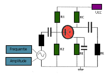
The model for the
simulation is a normal low signal amplifier circuit, which consists of a
standard transistor, an AC generator, some resistors and capacitors. The
model was developed for educational applications by Min and Malhotra (1988),
and Min and Van Leeuwen (1990, not published), in which the transistor's
behavior can be studied in a dynamic way by changing the input parameters.
 Figure 1.
Circuit of the simulation model

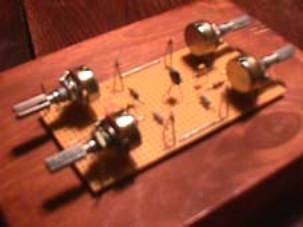
Figure 2.
Circuit board of the simulation model
|
Symbol
|
Notation
|
|

|
Transistor
|
|

|
Resistor
|
|

|
Capacitor
|
|

|
Battery
|
|

|
AC
generator
|
Table 1.
Notation of symbols in the circuit diagram
The default values of the parameters
and the starting values of the model are as following:
A
= 0.01 [V]
f
= 100.0 [Hz]
ui
= 0.0 [V]
beta
= 200.0
IC0 = 1.0 [mA]
q = 1.6E-19 [Asec]
K
= 1.38E-23 [J/K]
T
= 100.0 [K]
S
= 40.0*IC0 = (q / K.T).IC0 = 40.0
rb
= beta/S = 5 [kOhm]
Ucc = 12.0 [V]
IB0 = IC0/beta = 1/200 = 0.005 [mA]
IE0 = (beta + 1)*IB0 = (200+1)0.05 = 1.005 [mA]
RC
= 4.0 [kOhm]
R2
= 56.0 [kOhm]
RE = (0.5*Ucc - IC0*RC)/IE0 = 2/1.005 [kOhm]
Ir = (0.7 + RE*IE0)/R2 = 2.71/56 = 0.04839 [mA]
R1
= (Ucc-0.7-RE*IE0)/(IB0+Ir) = 174.0 [kOhm]
b
= ui*S/beta
uo = -beta*ib*RC
|